
Introduction
Selecting the correct cable tray size is an important part of electrical system design. A tray that is too small can create installation difficulties, restrict future expansion, and affect cable arrangement and thermal performance. A tray that is unnecessarily large can increase material, installation, and support costs.
One of the most important calculations in cable tray selection is cable tray fill capacity.
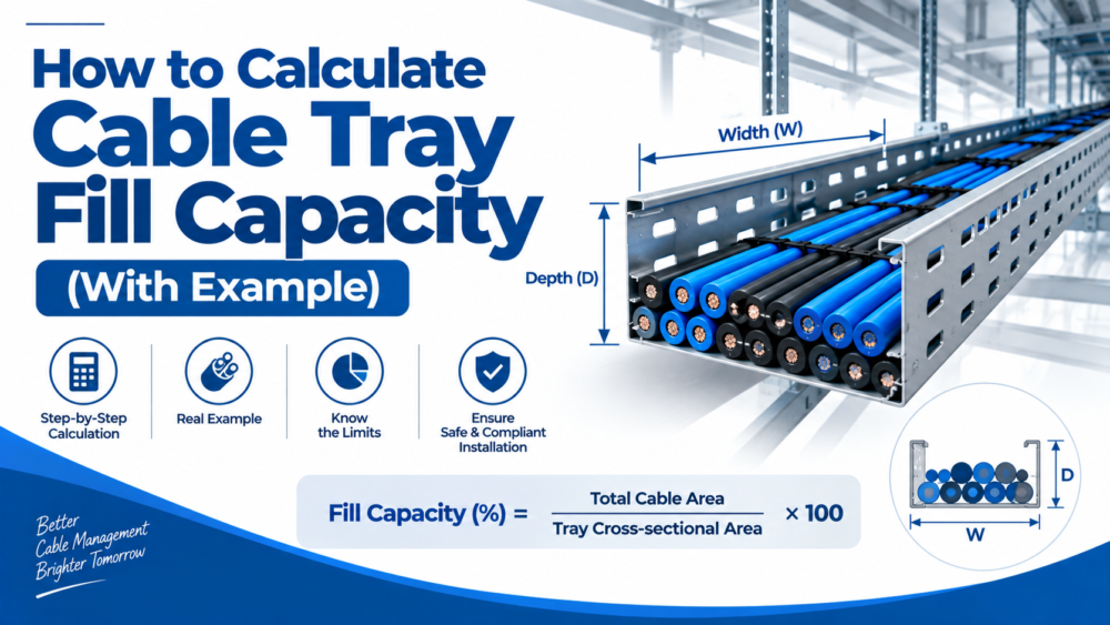
Cable tray fill refers to the amount of space occupied by cables inside a tray compared with the usable cable area permitted by the applicable design standard. The calculation helps determine whether a particular tray can accommodate the required cables safely and whether additional space should be allowed for future expansion.
In simple terms:
Cable tray fill calculation = Cable area required ÷ Allowable cable fill area
However, the actual calculation depends on several factors, including:
- Cable type
- Cable outside diameter
- Number of cables
- Cable arrangement
- Tray width and depth
- Tray construction
- Applicable electrical standard
- Cable voltage and size
- Future cable requirements
- Cable weight and tray load rating
This guide explains the basic method and provides a practical example.
What Is Cable Tray Fill Capacity?
Cable tray fill capacity is the maximum amount of cable that can be installed within a cable tray according to the applicable design requirements.
It is important to understand that fill capacity is not the same as the physical volume of the tray.
For example, a cable tray may physically contain a large number of cables, but the permitted cable area may be lower because of electrical, thermal, installation, or code requirements.
The permitted fill also varies depending on the cable and tray configuration.
For example, the NEC contains different cable-fill provisions for different types of cables and cable tray arrangements. Its tables distinguish between configurations such as ladder or ventilated trays, solid-bottom trays, and different cable combinations.
Therefore, a designer should always identify the applicable standard and cable category before applying a fill percentage.
Why Is Cable Tray Fill Calculation Important?
Correct tray sizing affects more than simply whether cables fit physically.
1. Prevents Overcrowding
Too many cables in a limited space can make installation and maintenance difficult.
2. Supports Cable Management
Adequate space allows cables to be arranged, secured, identified, and maintained properly.
3. Helps With Thermal Considerations
Cable grouping and installation arrangement can affect cable operating temperature and ampacity. Fill should therefore be considered alongside the applicable cable ampacity requirements.
4. Allows Future Expansion
A tray should not necessarily be designed only around today’s cable requirements. If additional cables are expected, spare capacity should be considered during the initial design.
5. Helps Select the Correct Tray
Fill is only one part of cable tray selection. The tray must also be capable of supporting the total cable weight and any other applicable loads.
Cable tray design guidance from Eaton, for example, treats cable weight, concentrated loads, environmental loads, and future cabling as separate load considerations.
Basic Cable Tray Fill Calculation Formula
For a simple area-based calculation:
Cable Fill (%) = (Total Cross-Sectional Area of Cables ÷ Allowable Cable Fill Area) × 100
To calculate this, you need to determine two main values:
- Total cross-sectional area occupied by the cables
- Maximum allowable cable-fill area for the tray
If the cable manufacturer’s data provides the cable outside diameter, the approximate cross-sectional area of a round cable can be calculated using:
Cable Area = π × D² ÷ 4
Where:
- π = 3.1416
- D = outside diameter of the cable
For multiple identical cables:
Total Cable Area = Cable Area × Number of Cables
Step 1: Identify the Cable Details
Before calculating tray fill, collect the cable information.
You may need:
- Cable type
- Cable size
- Number of cables
- Outside diameter
- Cable weight per metre
- Voltage rating
- Installation arrangement
The outside diameter is particularly important for an area-based calculation.
Do not estimate cable diameter from the conductor size alone. Insulation, shielding, armoring, and outer jacket construction can significantly affect the overall cable diameter.
The most reliable approach is to use the cable manufacturer’s technical datasheet.
Step 2: Calculate the Area of One Cable
For a round cable, use:
Area = π × D² ÷ 4
Suppose a cable has an outside diameter of:
20 mm
The cross-sectional area is:
Area = 3.1416 × 20² ÷ 4
Area = 314.16 mm²
So, one cable occupies approximately:
314 mm²
of cross-sectional area.
Step 3: Calculate the Total Cable Area
Now suppose there are:
20 cables
of the same 20 mm outside diameter.
Then:
Total Cable Area = 314.16 × 20
Total Cable Area = 6,283.2 mm²
Therefore, the combined approximate cross-sectional area of the 20 cables is:
6,283 mm²
This value can then be compared with the allowable cable-fill area for the selected tray.
Step 4: Determine the Allowable Fill Area
This is where cable tray calculations become more important.
Do not automatically assume that every cable tray can be filled to 40%, 50%, or another fixed percentage.
The allowable fill depends on the applicable standard, tray construction, cable type, and installation arrangement.
For example, NEC Section 392.22 provides different allowable fill provisions for cable trays and different cable configurations. In one set of provisions for multiconductor cables in ladder, ventilated trough, or wire-mesh cable trays, allowable fill area is based on the inside width of the tray.
This means the correct workflow is:
Identify the standard → identify cable type → identify tray type → determine allowable fill → compare cable area with allowable area.
Cable Tray Fill Calculation Example
Let’s work through a simplified example.
Given:
- Cable tray width = 300 mm
- Cable tray type = ventilated/ladder tray
- Number of cables = 20
- Cable outside diameter = 20 mm
- Cable type = multiconductor cable
- Cable arrangement = multiple cables
- Required standard = applicable project code/standard
First, calculate the area of one cable.
Cable Area = π × D² ÷ 4
= 3.1416 × 20² ÷ 4
= 314.16 mm²
Now calculate the total cable area:
314.16 × 20 = 6,283.2 mm²
So:
Total Cable Area ≈ 6,283 mm²
Next, the designer must determine the allowable fill area from the applicable standard for the selected 300 mm tray and cable configuration.
For illustration, if the applicable design requirement permitted an allowable cable area of 9,000 mm², then:
Cable Fill = 6,283.2 ÷ 9,000 × 100
Cable Fill ≈ 69.8% of the permitted fill area
The installation would therefore use approximately 69.8% of the allowable cable-fill area under this illustrative assumption.
The important point is that 9,000 mm² is an example of an allowable area for a particular code configuration, not a universal cable-tray fill value. The actual project calculation must use the applicable standard and exact cable/tray configuration.
A Simpler Example Using a Defined Fill Percentage
For preliminary planning, engineers sometimes use a project-specified allowable fill percentage.
For example, suppose:
- Tray width = 300 mm
- Usable tray depth = 50 mm
- Project-specified fill limit = 40%
The gross tray cross-sectional area would be:
300 × 50 = 15,000 mm²
At a 40% project-specified fill:
15,000 × 0.40 = 6,000 mm²
So the allowable cable area would be:
6,000 mm²
If the cables require 4,500 mm²:
Fill = 4,500 ÷ 6,000 × 100
Fill = 75% of the permitted fill area
This means the cables occupy 75% of the project’s allowed cable area.
Again, the 40% value in this example is only an assumed project criterion. It should not be treated as a universal requirement for all cable tray installations.
How to Calculate the Number of Cables a Tray Can Hold
If all cables have the same outside diameter, a basic calculation can be made using:
Maximum Cable Quantity = Allowable Cable Area ÷ Area of One Cable
For example:
- Allowable cable area = 9,000 mm²
- Cable diameter = 20 mm
- Area of one cable = 314.16 mm²
Therefore:
Maximum Quantity = 9,000 ÷ 314.16
Maximum Quantity ≈ 28 cables
This is a simplified area calculation.
The actual permitted number may be different because cable tray standards can impose additional requirements based on cable size, cable type, arrangement, ampacity, separation, and tray configuration.
For example, NEC provisions can require large multiconductor cables to be arranged in a single layer in certain cable tray applications rather than simply calculating their total area.
What If the Cables Have Different Diameters?
Many real installations contain cables of different sizes.
For example:
- 10 cables × 15 mm diameter
- 8 cables × 20 mm diameter
- 5 cables × 25 mm diameter
Calculate each group separately.
15 mm cables
Area = π × 15² ÷ 4
= 176.7 mm²
For 10 cables:
176.7 × 10 = 1,767 mm²
20 mm cables
Area = 314.16 mm²
For 8 cables:
314.16 × 8 = 2,513 mm²
25 mm cables
Area = 490.9 mm²
For 5 cables:
490.9 × 5 = 2,455 mm²
Now add them:
1,767 + 2,513 + 2,455 = 6,735 mm²
Therefore:
Total Cable Area ≈ 6,735 mm²
This total can then be compared with the applicable allowable cable-fill area.
Cable Tray Fill vs Cable Tray Load Capacity
This distinction is extremely important.
A cable tray can have enough physical fill capacity but still be unsuitable because of its load capacity.
For example, suppose a tray can accommodate the required cable area but the cables are very heavy.
The tray system must still be checked for:
- Cable weight
- Tray weight
- Support span
- Tray load rating
- Concentrated loads
- Additional environmental loads
- Future cable loads
Eaton’s cable tray design guidance identifies cable weight, concentrated loads, ice, snow, wind, and future cabling as potential components of total tray loading where applicable.
Therefore:
Fill capacity ≠ Load capacity
Both need to be checked.
Don’t Forget Future Cable Expansion
A common mistake is selecting a tray that is exactly large enough for the current cable installation.
Electrical systems often expand over time.
Additional:
- Power cables
- Control cables
- Communication cables
- Instrumentation cables
- Data cables
may need to be added later.
For this reason, the design should consider the project’s expected future requirements rather than simply filling the tray to its current practical limit.
Eaton’s cable tray design guidance specifically notes that if space is reserved for future cables, the tray should be capable of supporting the resulting future load.
How to Select the Correct Cable Tray Size
Once the required cable area and load are known, select a tray with appropriate:
Width
The tray must provide enough usable width for the cable arrangement and applicable code requirements.
Depth
The tray depth should accommodate the cables without creating installation or maintenance problems.
Load Rating
The tray must support the total expected cable weight at the specified support span.
Material and Finish
Select the appropriate material or coating for the installation environment.
Common options include:
- Pre-galvanized steel
- Hot-dip galvanized steel
- Stainless steel
- Aluminum
- FRP/GRP and other non-metallic systems
Support Spacing
The tray’s load rating is associated with particular support spans. A tray rated for one span should not automatically be assumed to have the same capacity at another span.
Common Cable Tray Fill Calculation Mistakes
1. Using Cable Conductor Size as Cable Diameter
A 16 mm² or 95 mm² conductor size does not tell you the complete outside diameter of the finished cable.
Always obtain the actual cable outside diameter from the manufacturer.
2. Using a Universal Fill Percentage
There is no single fill percentage that applies to every cable tray installation.
The applicable standard and cable arrangement must be checked.
3. Ignoring Cable Weight
A tray can pass an area-fill calculation but fail the required load capacity.
4. Ignoring Future Expansion
Designing only for the current cable quantity can result in expensive modifications later.
5. Ignoring Cable Arrangement
Certain standards place additional requirements on how cables are arranged, especially for larger power cables.
6. Treating Physical Space as Allowable Space
The geometric area of the tray is not automatically the permitted cable-fill area.
Quick Cable Tray Fill Calculation Checklist
Before finalizing a cable tray size, check:
- Cable type identified
- Cable outside diameter confirmed
- Number of cables confirmed
- Cable cross-sectional area calculated
- Total cable area calculated
- Applicable standard identified
- Tray type identified
- Allowable fill determined
- Cable arrangement checked
- Cable ampacity requirements checked
- Cable weight calculated
- Tray load rating checked
- Support span confirmed
- Future cable requirements considered
- Environmental conditions considered
- Suitable tray material and finish selected
Final Thoughts
Cable tray fill calculation is an important part of designing a reliable cable management system, but it should not be reduced to a single percentage.
The basic process is straightforward:
1. Identify the cables.
2. Obtain their actual outside diameters.
3. Calculate the cross-sectional area of each cable.
4. Add the cable areas together.
5. Determine the allowable fill using the applicable standard and cable/tray configuration.
6. Compare the required cable area with the permitted fill.
7. Separately verify cable weight, tray load capacity, support span, ampacity, and future expansion.
For a simple round cable, the area can be calculated using:
A = πD² / 4
And the resulting cable fill can be expressed as:
Cable Fill (%) = Total Cable Area ÷ Allowable Cable Area × 100
The most important point is that cable tray sizing is not based on fill alone. A properly designed tray system must accommodate the cables physically, electrically, thermally, and structurally.
For final engineering design, always verify the calculation against the applicable local electrical code, project specification, cable manufacturer’s data, and cable tray manufacturer’s technical documentation.
Frequently Asked Questions
What is cable tray fill capacity?
Cable tray fill capacity is the permitted amount of cable area that can be installed within a cable tray according to the applicable standard and cable configuration.
How do you calculate cable tray fill?
Calculate the cross-sectional area of each cable, add the areas together, and compare the total with the allowable cable-fill area specified by the applicable standard.
What is the formula for cable area?
For a round cable, the approximate cross-sectional area is:
A = πD² / 4
where D is the cable’s outside diameter.
Is 40% cable tray fill a universal rule?
No. A 40% fill value should not be treated as a universal requirement. Allowable fill depends on the applicable electrical standard, cable type, tray construction, and installation arrangement.
Does cable tray fill include cable weight?
No. Fill and load are separate considerations. After calculating cable fill, the tray’s structural load capacity and support span must also be checked.
How much spare capacity should a cable tray have?
There is no single spare-capacity percentage that applies to every project. Future expansion should be determined from the project’s requirements, applicable standards, and design specifications.
Can different size cables be installed in the same cable tray?
Yes, where permitted by the applicable standard and project design. The designer should account for the different cable sizes, arrangement, cable type, ampacity, spacing, and total allowable fill.
What information is required to calculate cable tray size?
At minimum, you typically need the cable type, number of cables, outside diameter, tray type and dimensions, applicable standard, cable arrangement, cable weight, support span, and future expansion requirements.
